
Archives
The Utah WaTCH
The Utah WaTCH provided information about development of the On-Site Training Program, regulatory information updates, news, and general on-site wastewater information.
Volume 1, No. 1 (Aug 1998)
Volume 1, No. 2 (Dec 1998)
Volume 1, No. 3 (Jun 1999)
Volume 1, No. 4 (Oct 1999)
Volume 2, No. 1 (Mar 2000)
Developmental Senior Design Team Projects

Senior Design Team 1999-2000: Development of On-Site Wastewater Training Site Design
The 1999-2000 Senior Design Team consisted of three members: Aaron Swank, Alan Miller, and Matthew Perry. The team developed and designed the future site of the Utah On-Site Wastewater Training Center that will aid in education and training of installers, inspectors, educators, and homeowners. The site includes training areas for conventional and alternative treatment systems, as well as areas for hands on experience in soil characterization(USCS Soil Classification Method) and pump sizing and maintenance.

Figure 1. Site Layout for the Utah 0n-Site Wastewater Treatment Training Program Site.
Each component of the Training Center was designed and drawn per Utah regulations for a 3 bedroom house situated on the soil found at the Orchard Site.The absorption systems will include "cut-away manholes" in order for visitors to the site to see "into" each type of system and better understand the processes taking place. Figure 2 shows an example of the "cut-away manholes" for the conventional systems.

Figure 2. Conventional Bed and Trench Absorption Systems with "Cut-Away" Manholes.
The second component of the Senior Design Project was developing the On-Site Wastewater Treatment Training Center website for outreach and continuing eucation purposes. The webpage will be updated by future Senior Design teams and the Training Center staff as the Orchard Site is further developed.
Senior Design Team 1998-1999: Development of Educational Tools for the Training Center
The 1998-1999 Senior Design Team consisting of five undergraduate students majoring in environmental engineering at Utah State University, designed and built several models to illustrate construction requirements of the mound system, which is an alternative on-site system that is being used in several areas in Utah. The students prepared the models as part of their Senior Design Project. The Senior Design Project within the College of Engineering is a yearlong academic course in which students work in teams to obtain hands-on experience with regard to three elements of engineering practice: (1) designing; (2) building; and (3) testing an applied engineering system.

Figure 3. Mound System.
The physical models consist of a table-top mound system that includes a profile that demonstrates the layering of materials in the construction of a mound. In addition, three plexiglass tabletop box models were constructed to demonstrate water flow through a typical mound. These models are used to illustrate the importance of plowing on water flow. The preparation of the interface between the mound sand fill material and the natural soil surface is critical to movement of treated wastewater into underlying soil. The interface must be gradual and diffuse to ensure that water moves into the soil and does not flow down the interface and cause failure at the toe of the mound. Such an interface is prepared by mixing the sand fill material with the underlying soil by plowing. The models include:
Non-sloped, plowed -- This model demonstrates the ease of water flow from the mound fill material into the underlying natural soil in a system built on level ground and with plowing of the fill/soil interface.
Sloped, plowed -- As with Model No. 1, even when the mound system is built on a sloping site, proper preparation of the fill/soil interface will ensure infiltration of the treated wastewater into the underlying soil.
Sloped, non-plowed -- This model, in which the mound fill and the natural underlying soil are not mixed, demonstrates the flow of water along the sloping and abrupt fill/soil interface, illustrating the potential for surfacing of the treated wastewater at the toe of the mound.
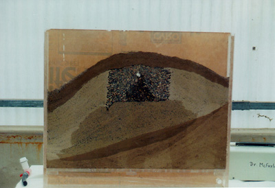
Figure 4. Sloped, Non-Plowed Mound Model. (Constructed by USU Senior Design Team).

Figure 5. Graphical Representation of a Mound System.

Figure 6. Table-Top Mound Model.
In addition, the computer model of a pressurized distribution system developed by last year's Senior Design Team was modified to make it more user-friendly and to provide a more useful output for designers of mound systems. The program is used to calculate the required number, size, and spacing of orifices in the pipes so that uniform distribution of wastewater effluent is maintained throughout the piping
The members of the Environmental Engineering Senior Design Team included: David Norman (Group Leader), Lance Allen, Shannon Johnson, Jeff Miner, and Ryan Roberts.
Senior Design Team 1997-1998: Development of Training Models
Five undergraduate students majoring in environmental engineering at Utah State University assisted the training center during the 1997-1998 academic year by developing practical training aids that included both physical and computer models of on-site treatment systems. The students prepared the models as their Senior Design Project. The Senior Design Project within the College of Engineering is a year-long academic course that allows students to work in teams to obtain hands-on experience with regard to three key elements of engineering practice: (1) designing, (2) building, and (3) testing an applied engineering system. Students work with faculty, staff, and industry personnel to consider project scoping, manpower and materials budgeting, project scheduling, design calculations, construction quality control, and testing procedures.

Figure 7. Pilot Scale Absorption Field Trenches.
Pilot-scale soil absorption field trenches to demonstrate the greater uniformity of flow in pressurized distribution systems than in conventional gravity-flow system. -- Two trenches were constructed in 2 ft (w) x 2 ft (d) x 20 ft (l) wooden boxes. The trenches were backfilled with gravel to a depth of two feet. For the gravity flow system, conventional 4-inch PVC pipe with perforations was laid on the surface of the gravel. The conventional gravity-flow trench is supplied water via a wooden reservoir. Water from the reservoir, simulating intermittent effluent flow from a septic tank, flows by gravity into the absorption trench.
Low-pressure dosing system -- The low-pressure pipe dosing system was constructed of 2-inch PVC pipe with 3/8 inch perforations. This pipe laid on the surface of the gravel, and fill materials were placed around the pipe to prevent splashing of the water. Water is distributed to this system from a garden hose under low pressure to simulate septic tank effluent dosed from a pumping chamber. In both systems, plexi-glass windows built into the sides of the trenches allow visual observation of the absorption bed.
Construction of bench-scale models -- Bench-scale, portable soil absorption field trenches to demonstrate the greater uniformity of flow in pressurized distribution systems than in conventional gravity-flow systems. A bench-scale demonstration model of gravity flow and pressurized flow was also constructed. The size of this model, including both flow systems, is 2 ft x 4 ft x 6 in and weighs approximately 25 pounds. It is also used to demonstrate the difference in flow distribution under gravity feed and under low-pressure distribution conditions. Movement of water can be seen by direct observation through clear plastic tubes as well as in wetting fronts as the soil moves through the "soil" (florist's floral foam). This smaller-sized bench-scale model can be easily transported to other sites for training.
Both the pilot-scale and bench-scale models demonstrate the greater level of uniformity in flow distribution along the pipe in the low-pressure system than through gravity flow.
Computer computational model of a low-pressure system to theoretically test pipe design -- The number, size, and spacing of orifices affect the head pressure that must be maintained in the pipe to achieve uniform distribution of effluent throughout the piping system. This software can be used to vary these parameters and obtain the desired outflow. It is a working program but is presently being modified to make it more user-friendly. The members of the 1997-98 Environmental Engineering Senior Design Project included: Byron Colton (Group Leader), Morgan Atkinson, Ross Gleason, Micah Nielsen, and Brent Seeley. Their advisor was Dr. Ronald C. Sims.
For further information about the "UTAH ON-SITE WASTEWATER TREATMENT TRAINING CENTER" please contact Judith L. Sims, Research Associate Professor, judith.sims@usu.edu.